Recent Articles
- Averaging with Sweep Count
- Generating Deembed Files with S2P Extractor
- The VISA Stack
- Basic SCPI Examples
- Calibrate for Reduced Partial Measurements
- ZNBT Parallel Measurements
Tags
By Year
Generating Deembed Files with S2P Extractor Nov 30, 2016
The S2P Extractor utility can be used to generate deembedding files for PCB traces, probes and fixture paths.
S2P Extractor works on the premise that the corrections generated by calibrating hold precise information about the networks that they calibrated out. If we perform two calibrations, one just before a particular feature and one that includes it, we should be able to compare the corrections that are generated to infer the response of the desired feature.
You can think of it as "subtracting" two calibrations to get the difference.
In this example, deembedding files are generated for a set of probe tips for use with a PCB. The same steps apply for generating deembedding files for a connectorized PCB or test fixture. The TRL calibration used in the example may be substituted with any calibration technique that generates full 12-term error corrections.
The example assumes the following equipment:
- Rohde & Schwarz VNA
- coaxial cables
- R&S Cal unit connected via USB
- RF Probes
- A printed circuit board with TRL standards on it

Installation
S2P Extractor is a free utility. It can be downloaded from:
S2P Extractor application page
Copy the installer onto the VNA and double-click to install. It is important to copy it onto the VNA hard drive; running the installer from a USB drive or mapped network drive may result in cryptic installation errors.
Once installed, S2P Extractor is available from the External Tools menu on the VNA.
For a ZVA:
System Config (hard key) -> "- More - (1/2)" (soft key) -> External Tools (soft key) -> S2P Extractor (soft key)
For a ZNB(T):
Applic (hard key) -> External Tools (tab) -> S2P Extractor (soft key)
Generating Deembed Files for a PCB
The following instructions assume that the VNA has already been configured for the desired measurement and deembed file settings (start frequency, stop frequency, points, power etc)
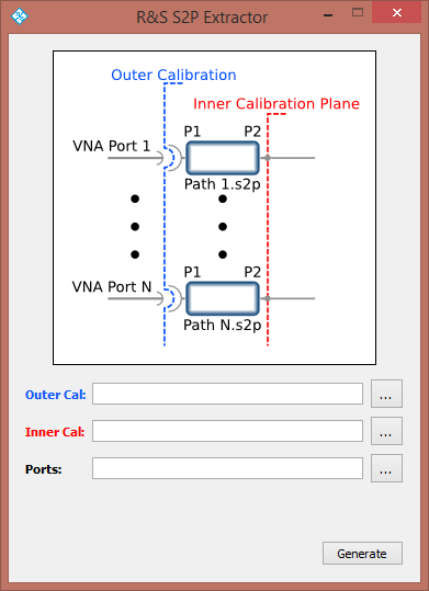
We will be performing two calibrations: an outer calibration and an inner calibration. The calibration planes for these calibrations are as follows:

The outer calibration is to the end of the coaxial cable, before the probe tip. The inner calibration plane is just after the probe tip.
Outer Calibration
The first step is to perform a UOSM calibration to the end of the coaxial cables using the cal unit. This should be easy, since (hopefully) the coaxial cables and the cal unit can be connected directly. Automated calibration with a cal unit is also fast.
This calibration should be saved as outer calibration for later use.

Inner Calibration
The next step is to perform the manual TRL calibration using the standards on the board. This is much more time consuming.
This calibration should also be saved as inner calibration for use later.

Generating Deembed Files
The corrections generated from the first (UOSM) calibration will have embedded in them the response of the system up to and including the cables.
The corrections generated from the second (TRL) calibration have embedded in them the response of the VNA, cables, and the connector+trace paths.
With some math, we can use the difference between the first calibration and the second calibration to generate the deembedding file for that path difference.
Open the S2P Extractor utility.
Specify the outer (UOSM) and inner (TRL) calibrations. Also specify the ports that were used.
Note: Single port (OSM) calibrations are not supported as of version 1.6. Support will be added in a subsequent release.
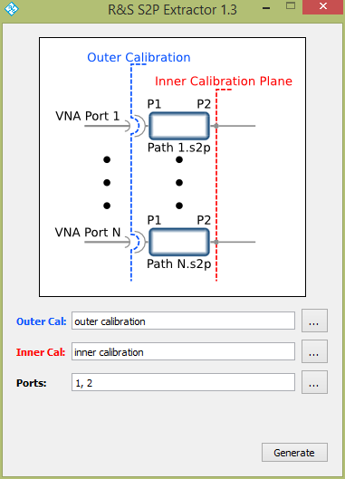
Click Generate.
The next window will ask you to specify a location and filename for the deembedding files. The files will be in touchstone (S2P) format, one for each path/port.
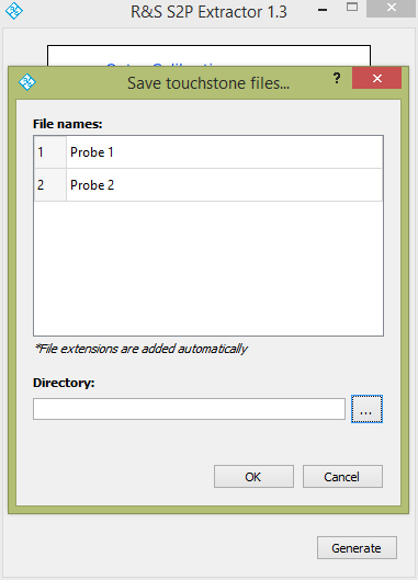
Click Ok
You should now have deembedding files for your board.
Applying Deembedding on the VNA
The deembedding feature of the VNA can be found in the following menus.
On a ZVA:
Mode (hard key) -> Virtual Transform (soft key) -> Deembedding at Single Ended Port (soft key)
On a ZNB(T):
Offset Embed (hard key) -> Single Ended (tab)
Note: The default touchstone file port ordering for S2P Extractor and the VNA matches. If both are left at their defaults, the deembedding should occur correctly.
Applying the outer (UOSM) calibration performed above and the deembedding files provides a calibration plane at the DUT. And, in the future, an outer UOSM calibration and deembedding will provide comparable results to performing TRL on-board without requiring TRL standards on-board or performing a time consuming TRL calibration.
This should will be accurate so long as the board characteristics aren't changed, either by design change or through drift over time.